As per title, after purchasing two receivers last year I managed to get round to fitting it this afternoon after a few productive days around the car.
This should not take more than one hour if you have the correct tools, you know what to do and are not scared of taking things apart.
Cost of the receiver from Audi is around £40 depends on the discount you can get and the cost of the plug which you can get either from Audi as well or eBay for around £6
Part numbers:
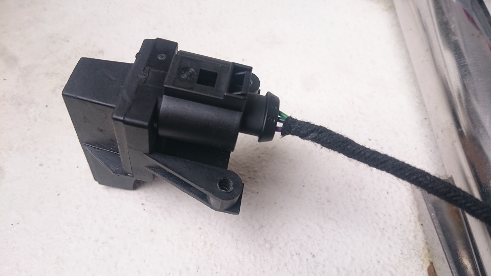
Radio receiver 4B0 919 145 B
Plug 3D0 973 703
http://www.ebay.co.uk/itm/1415809412...%3AMEBIDX%3AIT
I started with wiring the plug for the receiver base on this diagram.
I have used 0.5 wires instead of 0.35 as that is what I have left after AFS retrofit which I have completed last weekend and a separate thread will follow up shortly, also colours of wires are different.
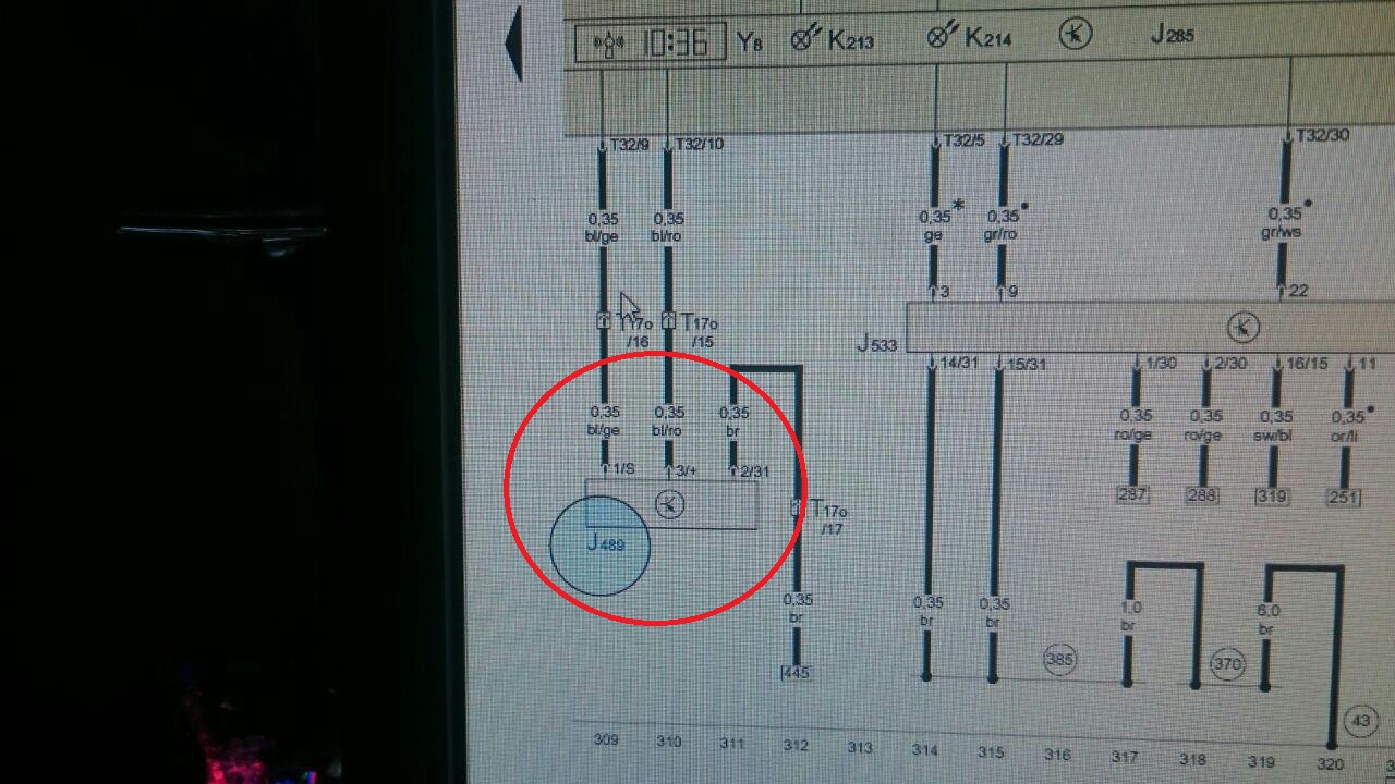
Please note that pins on receiver are in different order than on the plug.
Plug pins are 1 - 2 - 3
Receiver pins are 2 - 3 - 1
Pin 2 is marked on the receiver, first one from the left

I have used terminal connectors for 0.5 wires not much thicker ones which are supplied with the plug from eBay link
N 103 357 06
and N 907 647 01 for the connector on the back of the cluster

So, that is the plug wired and wrapped with a fabric tape for wiring looms
I prefer TESA brand tape, £4.49
http://www.ebay.co.uk/itm/25m-x-25mm...item56655e45d8


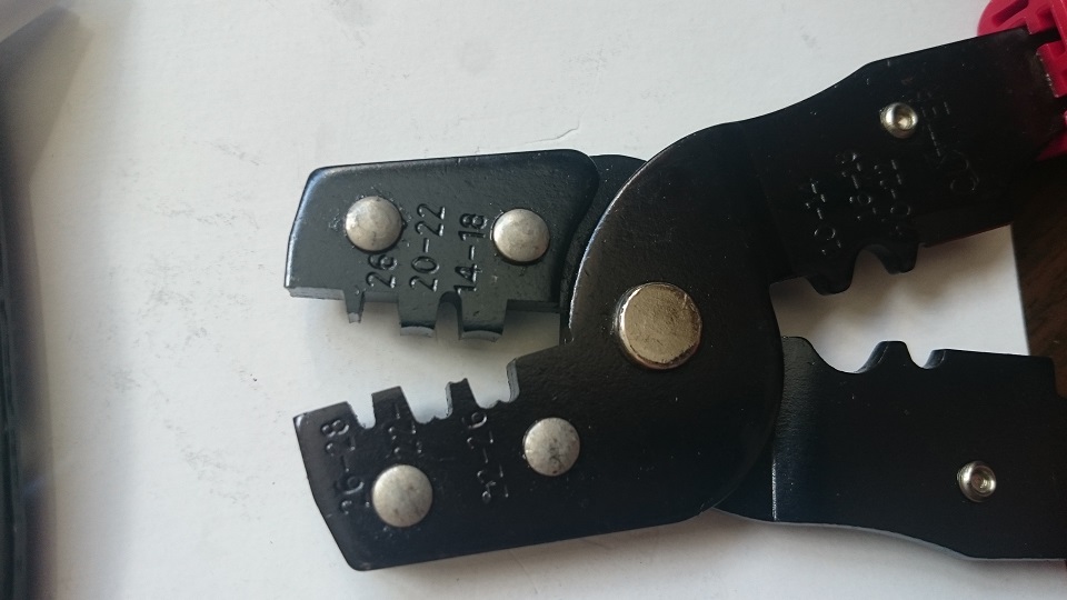
I've used the JPT crimping tool which is the best tool you can have for any electrical repair/mods around the car, £19.99
http://www.ebay.co.uk/itm/1716253073...%3AMEBIDX%3AIT
Removing cluster:
Remove the thin dark grey plastic trim from the dashboard which runs just under your wood/carbon trim.
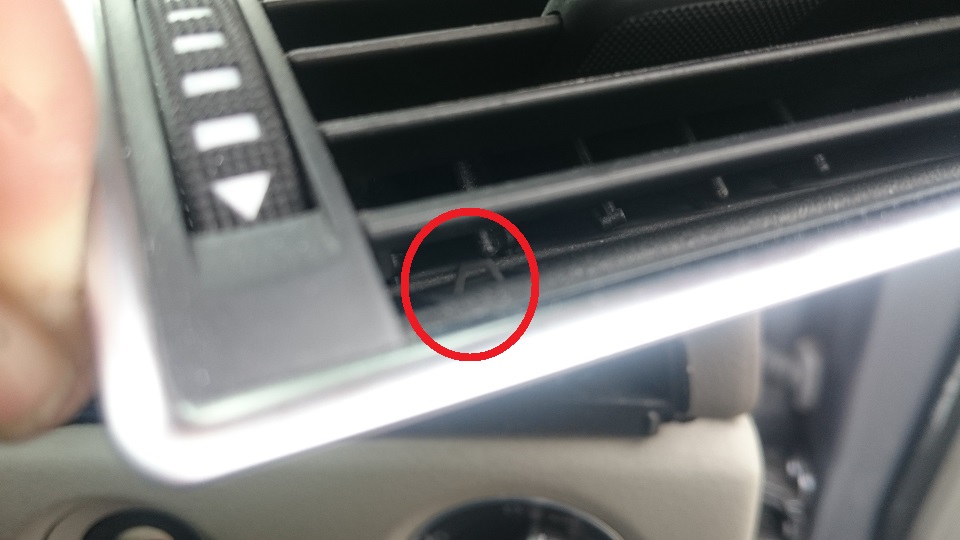
Next remove the air vents. There are two locking clips on each vent, use a thick ish, not to flexible, steel wire bend in U shape or use two very small allen keys. Lift the clips and pull the vent out but be carefull as there is a electrical connector on each vent.


Next undo the hex bolts as per pictures below and pull the cluster's trim.
Before you do that:
- insert the key to ignition and turn it right
- lower and pull out the steering wheel as far as possible
- turn the ignition off, left, but leave the key to stop the steering wheel going into exit position (up)
- indicator lever down
- hold wipers lever down while removing the trim


Next on each side of the actual cluster there are two metal retaining (silver) brackets, sorry no picture, push them out to the side and pull the cluster out.
This is a bit fiddly but nothing to hard. Wiring loom is fairly long so keep turning and moving the cluster until you will have an easy access to the connector on the back which you will have to disconnect.
Originally receiver is installed behind the rear bumper, in all honesty, I couldn't be bothered to go through so much hassle in order to have this retrofit which would involve rear bumper removal and running wires from the rear bumper to the back of the cluster. Call me lazy but I've done a lot of much more significant and complicated work around the car so I basically could be bothered. Plus previous 8s had them fitted behind the cluster anyway.
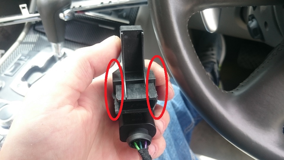
In order to fit the receiver behind the cluster you will have to chop off two fixing points with cable cutters or whatever you have in hand.
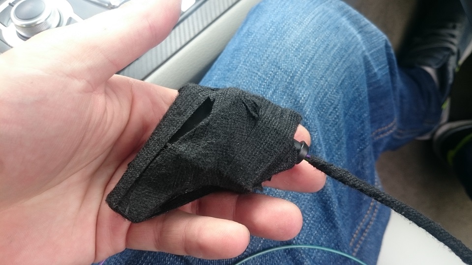
Then I wrapped the receiver in fabric tape to prevent any possible ratling or whatever.
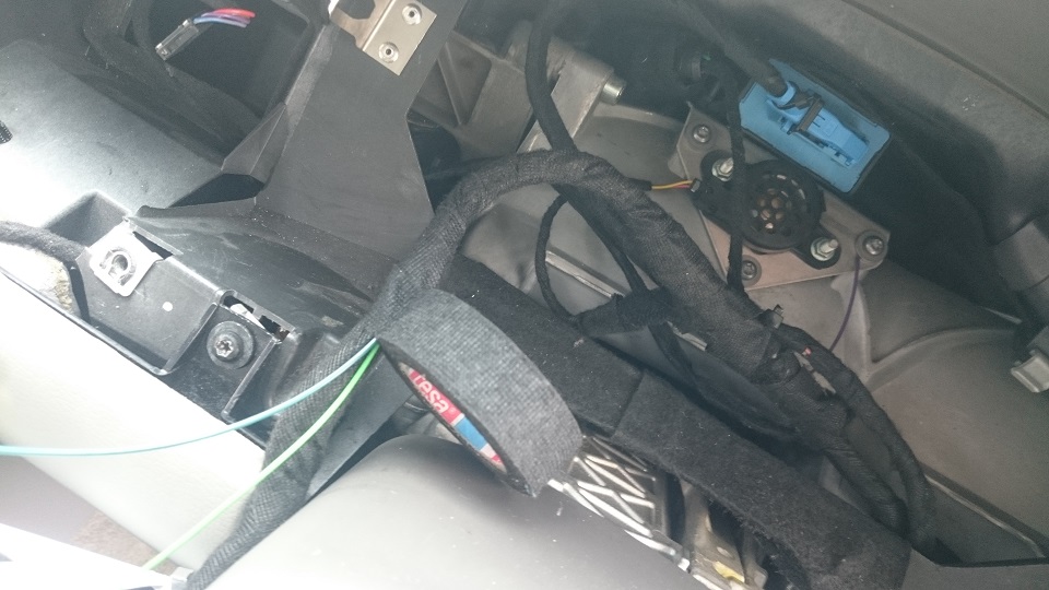
Best location is on the left of the Xenon Range Module (black box with blue connector). There is an open space on the right but nothing to rest on the receiver will just fall through.

As earth (purple wire) I have used the bolt for the Xenon Module bracket.
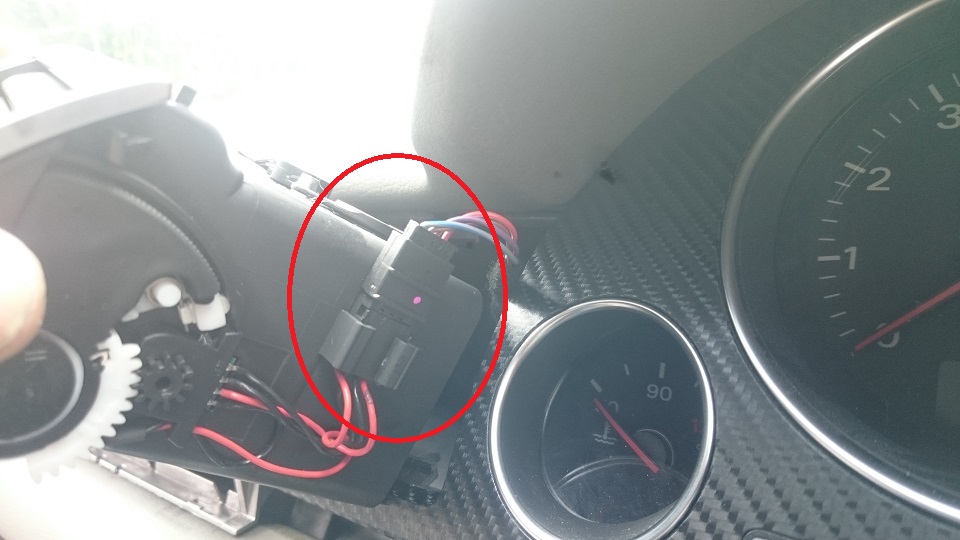
I taped the wires to the existing cluster wiring loom.
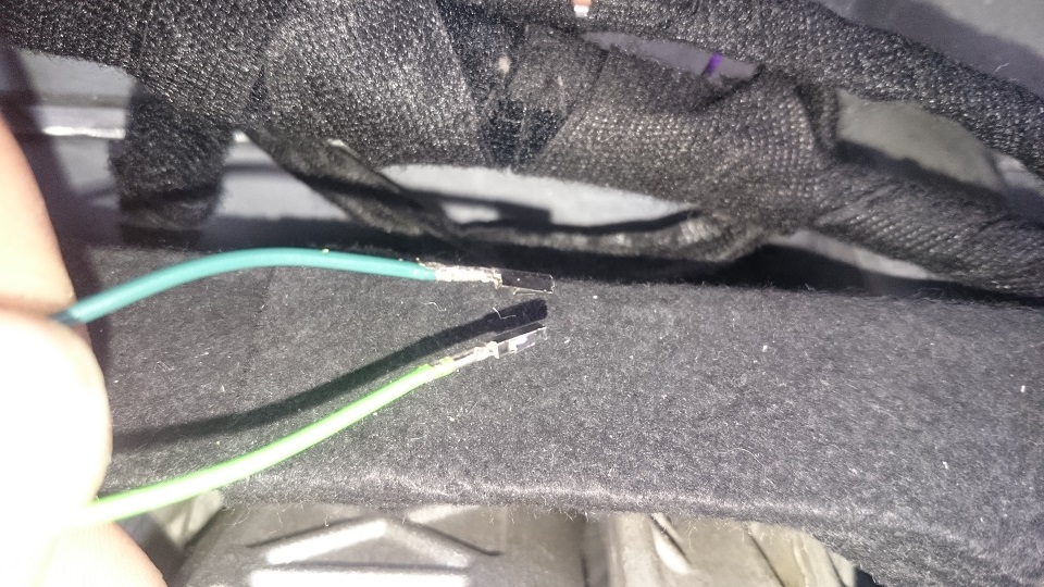
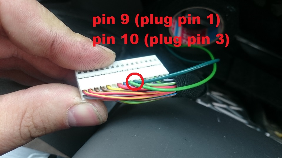
Then I crimped the connectors to the green wires and took the cluster's connector apart in order to plug them in in the position of pin 9 and 10.
Then I just finished taping the loom and new wires together and thats it.


Put all back together and next VCDS
Go to [17] Instruments
then Adaptation
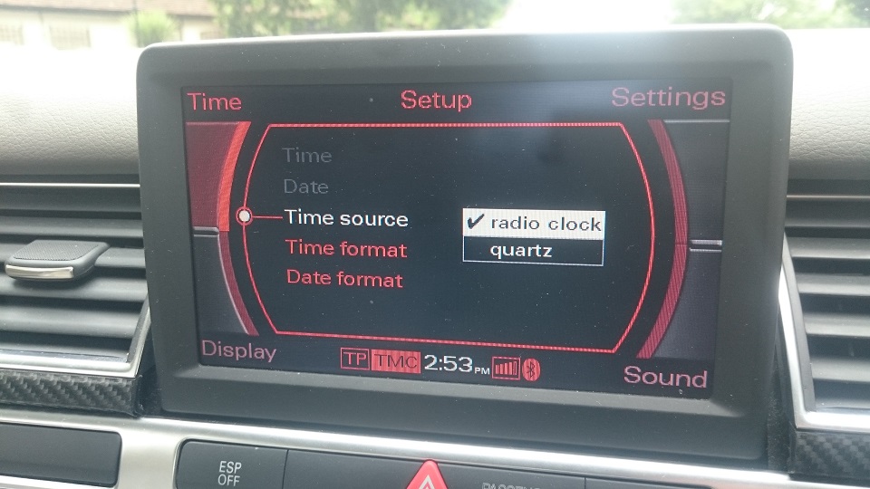
select Radio Controlled Clock from the drop down menu
Change New Value from 0 to 1 or as per instructions in the picture below (1-50 - minutes)
TEST
SAVE
DONE, GO BACK
Exit Controller, close VCDS, unplug the cable and you are done.


Not sure if on D3 there should be an icon of radio tower like on the D2s, but I assume thats only when receiver will receive the signal from the radio tower in Frankfurt, and from my experience with radio controlled clocks this may take a while and its sync process is only at certain times or something like that.
....or, I messed up something
")
__________________
 2006 D3 S8 5.2 V10
Ceramic Brakes, Bang&Olufsen, DTV, DAB, Rear Camera, BT, TPMS, Soft Close, Auto Boot, AMI , 4 Zone AC, Home Link, All Electric Blinds, Fingerprint, Ski Hatch, Black Extended Leather, Heated Sport Seats, Alacantra, Carbon Trim inc Aluminium Pack 2.
2015 A3 S line 1.4 TFSI - for the missus to keep her away from my car.
Standard S-line equipment, no extras.
2006 D3 A8 3.7 V8 - SOLD but not forgotten