I've been making parts for the manual swap so I thought I'd show how to go from concept to physical part.
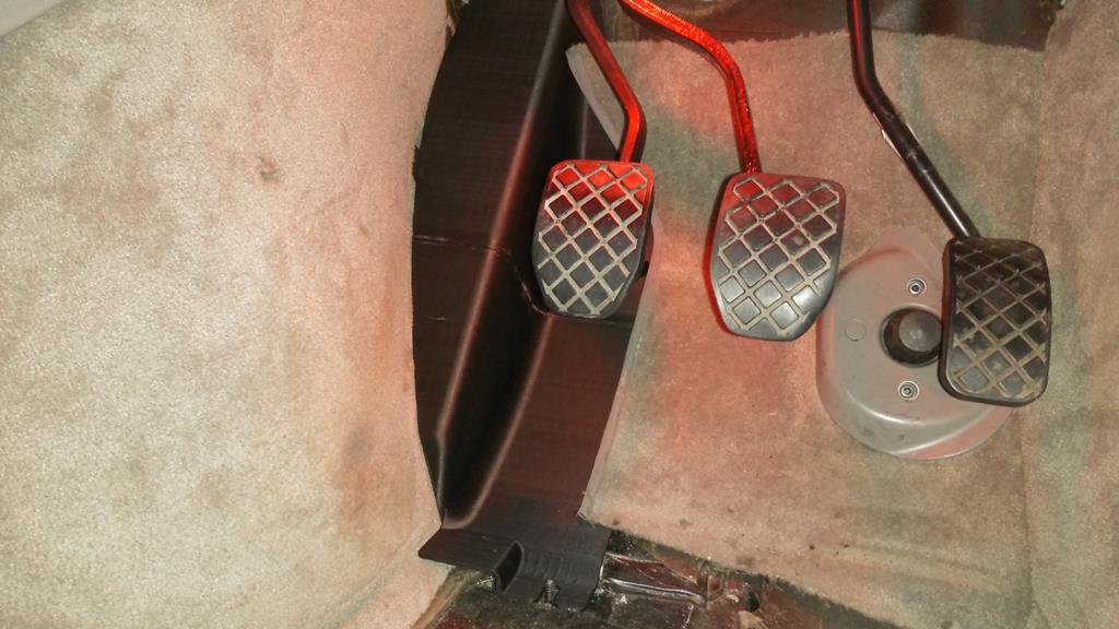
The original footrest has to change to make room for the clutch pedal, and rather than mucking around with the original I thought I'd just print a new one.
I started by tracing the outline of one edge of the original footrest on to a piece of A4, and then scanned it in as a tiff image:

Next, I used an online service to convert the tiff image from a bitmap to a DXF vector drawing. This is effectively a point cloud so not that useful yet.
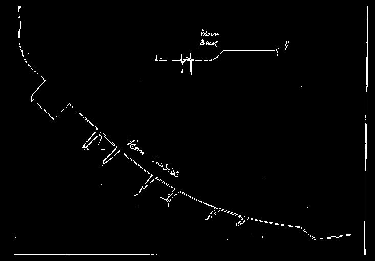
I made the DXF in to a background layer in Autocad and then drew the shape over the top of it. This time its a nice CAD drawing using lines and arcs.

I imported the drawing in to Fusion360 and extruded it. Now we're getting somewhere

After a few hours of measuring the original and making some changes as I went along I got to this
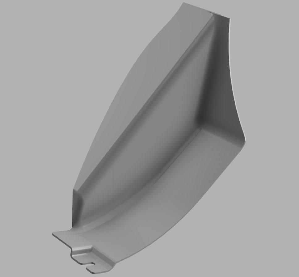
Added the final detail and the 3D model is done
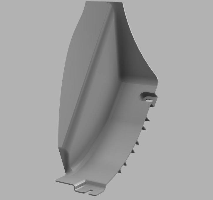
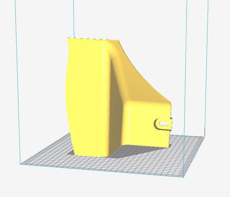
This would actually fit on my printer in one piece, but because of the angles it would need a lot of support structure. That takes a long time to print, and also adds a lot of risk as the support is very weak and its easy for the print head to knock it over resulting in a failed print. To avoid that, I cut it in half


Loaded the first half in to Cura for slicing. 20 hours to print...
First print done

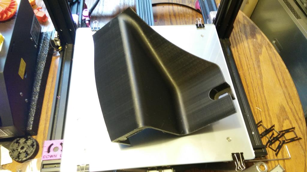
Second print done

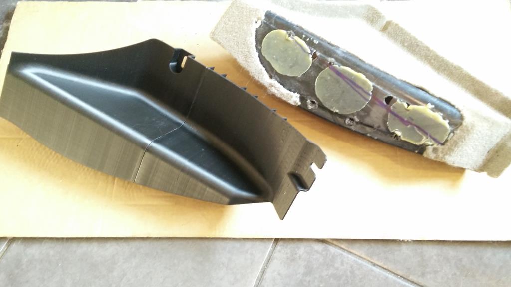
Glued together and next to the original
Installed. I'm pretty pleased with how it turned out, although I'll make some changes to the next one to speed up printing and improve strength.