
|
|
|||||||
| D3 - Lights Headlights, xenons, foglights. Everything outside the car that glows |
|
|
Thread Tools | Display Modes |
|
#1
 16th October 2013, 01:18 PM
|
||||
|
||||
|
Ok this tut is for the Audi A8 D3 rearlights, it will help in the removal of trim prior to working on the lights and to run extra wires as per the Audi wiring diagrams ( wiring has still to be proven to do anything on a Euro car and may only apply to US market)
Please read the comments properly as not everthing can be photographed, as such I have tried to explain as clearly as possible the other elements of doing this work. We are going to start off with the Boot / Trunk Lid lights. The first part you will want to remove is the Toolbox this is held in place by 5 phillips head screws that are under the caps pictured below that can be prised out using a small flat blade screwdriver or similar. 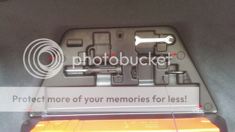 Now that you have that removed you will want to remove the light by gently levering it out on the edge nearest the grab handle. 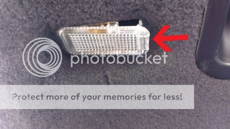 Once you have the light out of the hole, remove it from the cable harness and poke the harness back into the Boot lid. 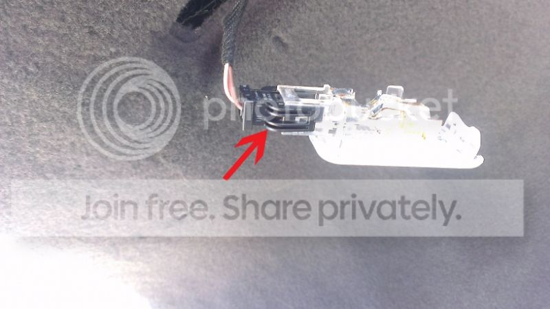 Now you need to remove the cover that goes over the latch mechanisim, just grab it firmly and pull it straight off. 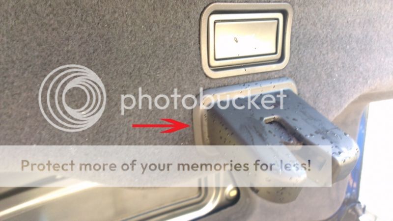 Next up is the two grab handles, there is a flap covering two phillips screws that needs to be prised open, then remove the screws and the handle pulls out easily. 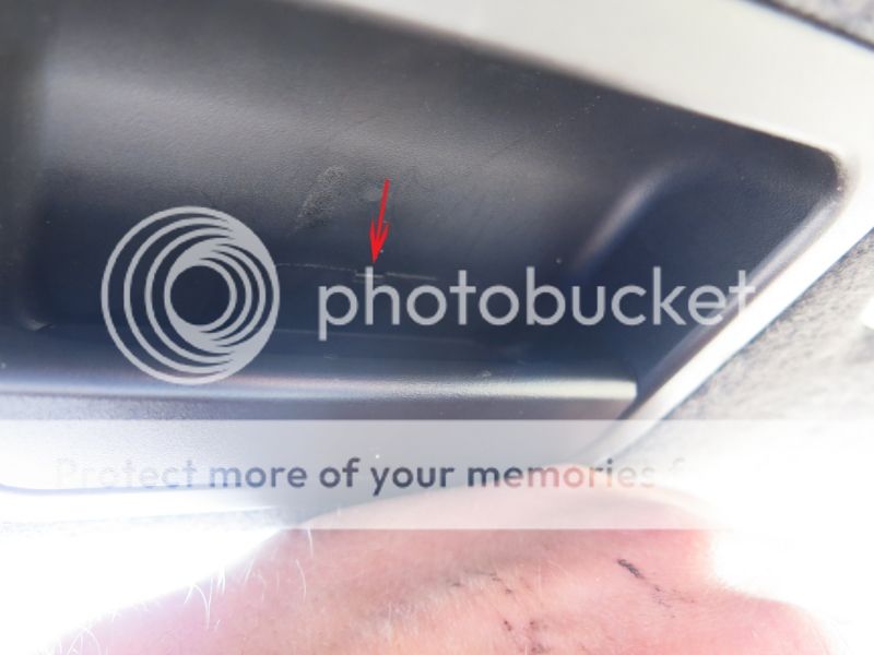 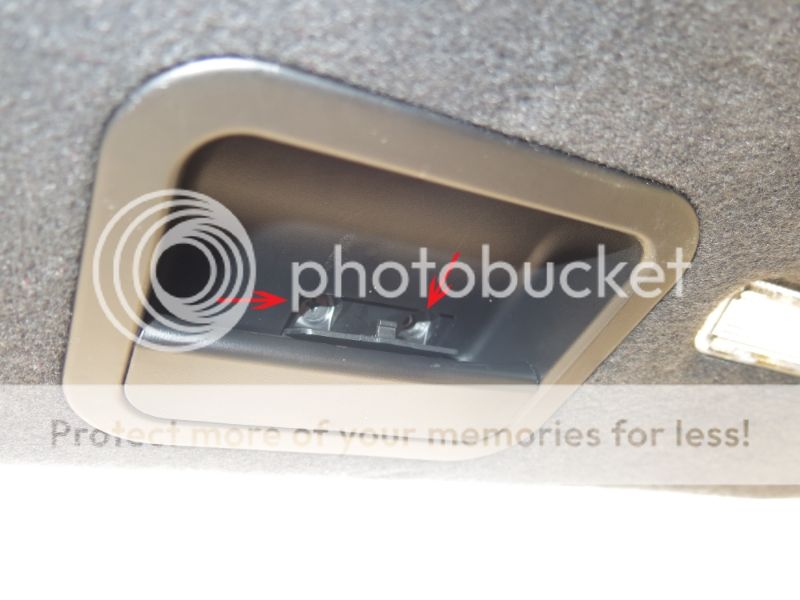 Now at this point I removed the cover without removing the Boot lid close switch as it looks like it could be easily damaged, so I carefully popped the clips on the cover and once it was released I disconnected the wiring from the switch leaving it in the cover. 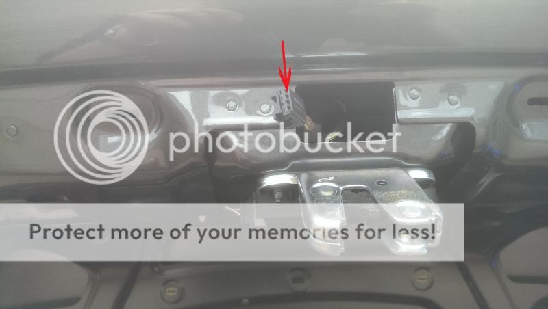 The choice is yours! You can see in the following image the locations of the clips that need popping out. I started at the bottom edge in the photo below with the two arrows by putting my fingers between the cover and Boot lid and pulling straight out. All the clips should be popped perpendicular to the panel like the first two. 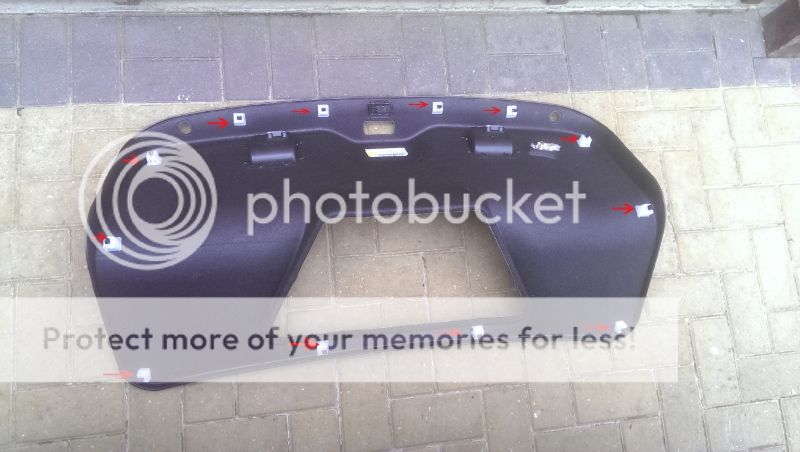 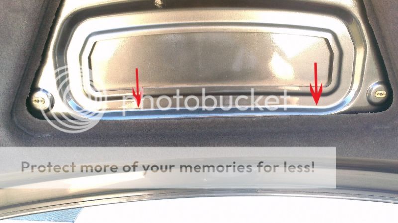 Now you have the cover removed you will see the cable harness securing clips that poke through the lid. Push the ribbed pin in the picture up into the void to enable you to take the connection out of the void. Once you have the connection on the outside unplug the two halves and then remove the mounting pin, it just slides off after lifting the tab a bit. The reason for removing the mounting pin is the plug will not fit out through the hole in the bootlid when you remove the light unit.     Now that the mounting pin has been removed follow the cable harness from the plug towards the light and you will feel a rubber grommet where the cable passes to the outside. Push the grommet clear of the bootlid, you can now remove the three nuts (8mm) securing the light unit to the bootlid and remove it carefully while guiding the remaing cable harness and plug out through the hole in the lid.   If you are just replacing like for like then its just a reversal of the process as far as the bootlid lights are concerned. That said if you are fitting old lights back in then you will need to purchase double sided adhesive foam tape to adhere the trim to the boot lid, This can be bought at Maplin. For alignment of the inner light see the following image, I found the process easier if you nip the nuts up finger tight so the unit is snug to the panel then screw the stud in or out to get the light flush with the panel. It will take trial and error and a remember to check with the bootlid closed to see if the panel gap follows neatly. Once you are happy with the position remember to tighten the nuts before going any further.  If your retrofitting facelift lights and want to run the extra wires then continue on. As I was fitting the Facelift lights to a early 2007 car it did not have the wiring in place for pin 7 on the new light cluster, so I ran the extra wires to the Control unit in the right hand side of the boot. As yet it still remains to be seen that the extra wires do anything and it may be only applicable to the US market. (Time will tell) Items you will need to run extra wires are :-
Ok on to the task in hand, now you have the Bootlid lights in place I started by un-clipping the cable loom that runs on the right side bootlid hinge. Un clip it by pulling on the top edge carefully to get it off the hinge bracket.  Once you have it off, pull the plastic tube from the support that you just pulled off, then roll back the rubber parts either end of the tube to expose the cable harness inside. Once you have done that lube the end of the pull wire and feed through the tube as in the photos below.   Once that is in place attach the speaker cable to the clean end using electrical tape, making sure to tape it 4 - 5" along the pull wire tightly and not making it too thick or you will struggle to feed it through. Once attached lube the cable and pull it through the tube like the next photos.   I then pulled the rubber boot out of the bottom right hand corner of the bootlid and fed the pull wire through the rubber trunking and repeated the process to get the speaker wire through that section and up into the bootlid. Use the stiff wire to assist getting the wire up from the corner of the bootlid and out, I pulled through quite a bit as you don't want to be short later on.   Once you have the wire into the bootlid split the shotgun speaker cable and route to where the two harness terminate and tape it to the original loom to prevent it ending up in places it shouldn't  Now repeat the cable pulling through the other rubber tube by pulling out the end next to the right hand light as in the next picture, using the same technique feed the speaker wire through and leave hanging for now.  Now we need to add the extra terminal to the two plugs, as stated earlier the terminal comes with two ends attached to one piece of wire so cut it in half. Open the side of the plug 1,3,5 & 7 like below and a insert the new contact in position 7 making sure you have looked at the orentation of the other contacts so you fit the new one correctly as they are not meant to come out once locked home in the plug.     Once you have fitted the contact and closed the plug you will need to solder the wire to the cable you ran. Cut the wires to length and bare the ends ready for tinning, tin the ends with solder and once cool cut a piece of heatshrink and feed over the end of the wire. Now solder the two wires together and then heatshrink to seal the join. 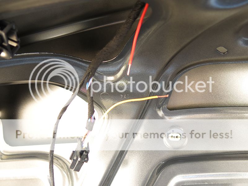   The more observant among you will have noticed the different wire colours above, I ran the red wire to the Left side light unit as Red is Port on a ship so it was easy for me to remember later on when the other end gets connected. What ever colours you have a choose be sure to make a note so you dont get them mixed up later when it gets connected to the control unit loom. Repeat the above on the other plug and you are ready to move on. Now you will need to remove the outer lights, the plastic trim that rests against the light is stuck on with double sided tape and will need peeling away from the light unit. Remove the caps and inside there are two 12mm nuts holding the light unit in. Using a 12mm socket fill it with blutack or something like that so that the nut sticks in the socket, otherwise you run the risk of losing them into the guts of the car never to be seen again. (Like me  ) )   With the outer lights removed we can finish running the wires to the inside of the car prior to fitting the lights back in. Feed the cable boot and speaker wire through to the space for the right hand outer light as shown.  Now pull out the grommet that goes to the inside of the car  Now pierce a hole through the grommet in this location.  Feed the speaker wire through the pierced hole and into the inside of the car, then refit the grommet and seal the cable and hole with some silicone as shown. Now tidy the cable routing by taping to the existing loom.  Now the wiring has been routed you can get on with fitting the new outer lights, they are plug and play but will most likely need adjusting to sit correctly in the bodywork. I did not have a female torx bit small enough to agjust the lights while in situ so had to go through the process of putting them in, looking, taking them out, adjusting the bolts and try again till I was happy with the levelness of the units. Once your happy with the levelness etc pull the light out again and cut and fit some adhesive foam tape shown in the image. Please bear in mind that if your not careful you will lose the securing nuts into the car body. If you do lose some take the adjusting nuts off the old lights. 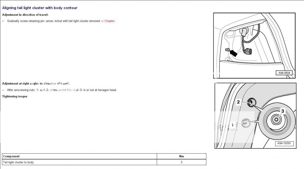 Now your lights are all bolted in its onto finishing the wiring. 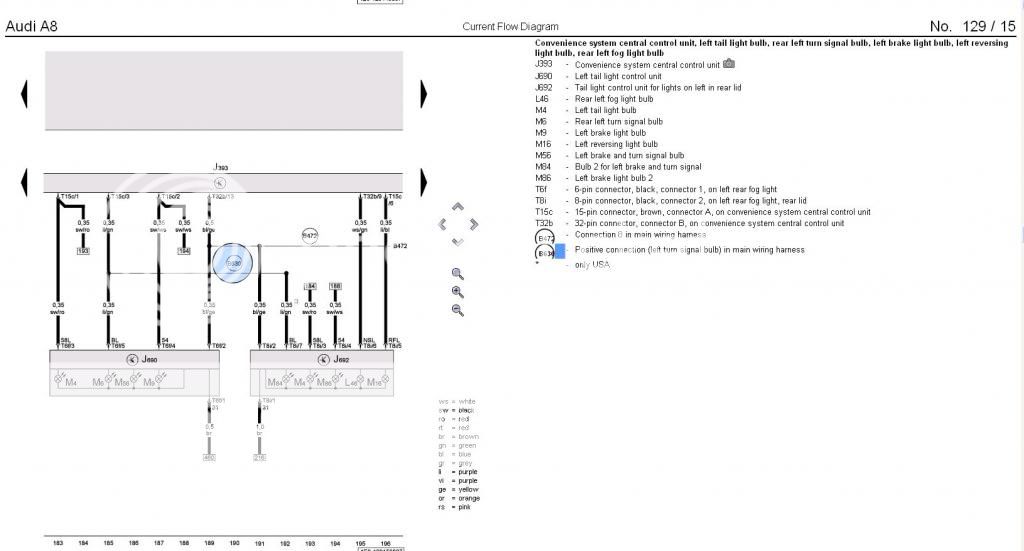 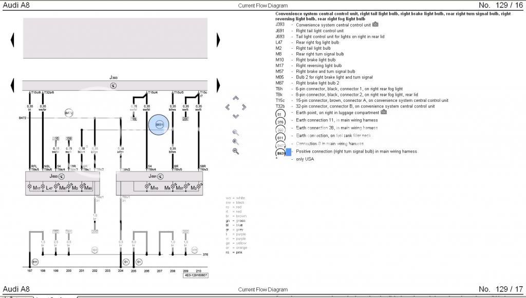 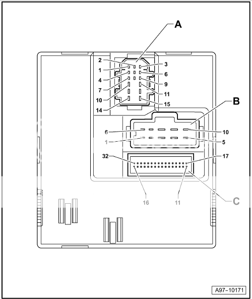 We can see from the wiring diagrams that the left light has extra wire (B630) with a colour of Purple/Green and following the diagram back to J393 it goes to pin 3 of the 15 pin connector (A) The right light has extra wire (B631) with a colour of Blue/White and it goes to pin 5 of the 15 pin connector (A) If you ran the wires as I did with the same colours then you will splice the Red (Port) wire into the Purple/Green on Pin 3, and the Black wire spliced into the Blue/White Pin 5 You will already have removed the right hand side cover in the boot to feed the wire through to the inside of the car and while laying in the car if you look up to where the wiring comes through from the light area you will hopefully see something like this. Notice the Speaker cable hanging down form the grommet.   Now looking up inside you can see the Central Convenience Unit (J393) Disconnect the upper brown coloured plug (15 pin Connector A)  It is wrapped in Coroplast loom tape, carefully cut it open near the plug and unwind it back allowing you to splay the wires open   Now locate pins 3 and 5 Purple/Green & Blue/White and cut them 3" back from the plug and using the same soldering procedure from earlier splice the new wires into the loom as shown in the photo.  Now tidy the loom back up and plug it back in to where it came from.    Only thing left to do now is tidy up that bloody mess you have just made, test everything, once your happy pull the adhesive tape covers on the inner lights like below and refit all the trims.   Now go have a few of these  
__________________
Del 
Last edited by Delboy; 17th October 2013 at 03:47 PM. 
|
|
|


 Threaded Mode